IoT Prototyping Series: Building an IoT Plant Cultivation System Pt. 2
In our last blog post, we discussed why I chose to create my very own IoT plant cultivation system and went over the preparations involved. Check it out for yourself here.
If you’re building your own plant cultivation system you’ve likely been looking forward to this next step.
So let’s jump into the fun part: building and assembly!
Hardware Setup: Connecting the Sensors
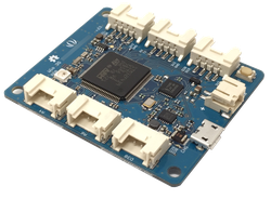
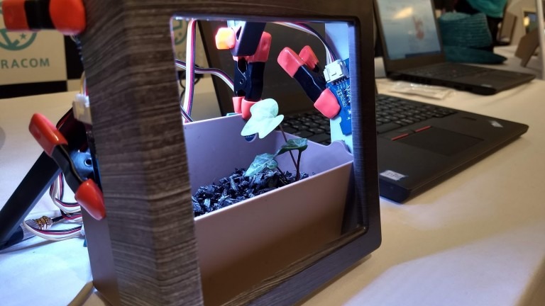
Seeed’s Grove system makes it very easy to connect the sensor to the Wio 3G unit, so the hardware was set up in no time.
All I had to do was connect the analog sensor to the analog terminal and connect the I2C sensor to the I2C terminal. Since Wio 3G is an eSIM, there is no need to insert a SIM card.
Connect to the PC with the USB cable of the power supply, connect the antenna to the antenna terminal, fix each sensor and LED, etc., in the temporary position, and everything is ready in terms of hardware. In addition, I used something like a “quick release hobby clamp”, “handy clamp,” or “spring clamp” to temporarily fix the LED and sensor to the container where the plant is planted.
All of these have a resin cover at the end, which makes it hard to damage the board or sensor and can be temporarily fixed simply by pinching it, making it easy to perform trial and error and convenient.
Installing the LED Lighting
With the hardware setup complete, I wrote the software and lit up the LEDs. The library that we used for the LEDs this time was provided by Seeed on Github, however, it turns out that it can only be used with ESP32 CPU (Wio 3G uses STM 32 CPU).
To solve this, I decoded the data sheet of the LED and made it usable on STM32 (you can find the source code for this here).
As I mentioned above, I believe in the theory that two wavelengths of red (660 nm) and blue (450 nm) are the key to growing plants, and I initially thought I would only shine the red and blue (B) LEDs. However, then I say that the light became pinkish light (magenta). Plus, the green color of the plants wound up looking black, which was not very appealing, so we decided to use all red, green, and blue, turning them into white light.
Smart LED Control with SORACOM Funk
Turning on the LED lighting was easy enough now, but I needed to know the current time to turn it on / off at the right time. At first, it was difficult to get the current time, so in the morning, I connected the Wio 3G to the power supply and started operation, and at night I controlled it manually by disconnecting the cable from the power supply.
But on days when my return home is delayed, the plants keep being exposed to light. Wio 3G has an RTC (Real Time Clock), but the clock is reset when the power is turned off, so every time it starts up, you need to get the time from somewhere and set it in the RTC No.
There are ways to get the time from a 3G network or to set the clock with NTP, so even if you can set the clock, there is still a problem. For example, if you set the LED irradiation time to 12 hours from 6:00 am to 6:00 pm at first, but want to change the setting later, the device will have the on/off time setting. If so, it will take time to change.
The Wio 3G side does not have any time setting, and when uploading data to the server, the server-side judges LED on/off based on the time, etc. and returns only the judgment result to the Wio 3G side as a response Then, Wio 3G decided to simply turn on / off the LED according to the result.
For that purpose, I prepared a function of AWS Lambda and wrote a simple program that turned on after 6:00 in the morning and turned off after 8:00 in the morning. In the future, this control part will be able to sync the on/off to the actual sunrise/sunset time. Plus, the brightness of the LED will gradually increase instead of being always on at 100%, replicating natural sunlight.
To invoke AWS Lambda functions, I decided to use SORACOM Funk; however, when I did this prototype, Funk was under development and I couldn’t use it yet, so I used SORACOM Beam to call Lambda via AWS API Gateway.
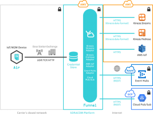
At that time, instead of directly calling Beam or Funk from the device side, it was made to go through Unified Endpoint. By doing so, there is no need to change the device side, and you can easily switch the call destination from Beam to Funk.
Also, as we will see later, we also wanted to use Soracom Lagoon for visualization and alert notification, so we used Unified Endpoint to send data to Beam, Funk, and Harvest. With this setup, changing the configuration of Funk and Harvest was very easy.
The great advantage of Unified Endpoint is that it is easy to make such flexible changes. In addition, between the method of calling Lambda from Beam via AWS API Gateway and the method of calling Lambda directly using Funk, the latter Funk is obviously easier, but the format in which the response returned from Lambda arrives at the device were slightly different, so in fact it was not possible to switch smoothly. Still, we were able to switch without having to make such a big change, so that wouldn’t be a big problem.
The Final Step!
Are you following along and building your own plant cultivation system? In the next part of this series, we’re going to be testing the CO2 sensor and visualizing the data using Soracom Harvest and Lagoon. See you then!


