SmartAgro
Things used in this project
Hardware components

|
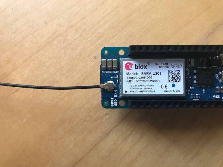
Arduino MKR GSM 1400 | × 1 |

|
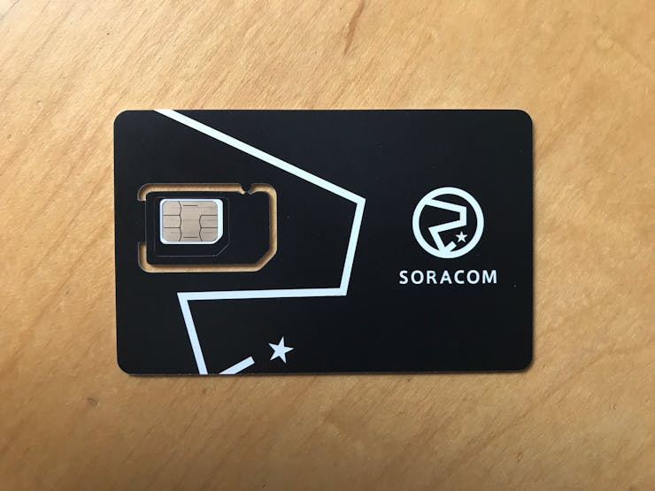
SORACOM Air Global IoT SIM | × 1 |
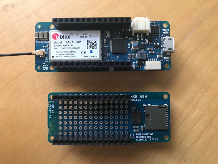
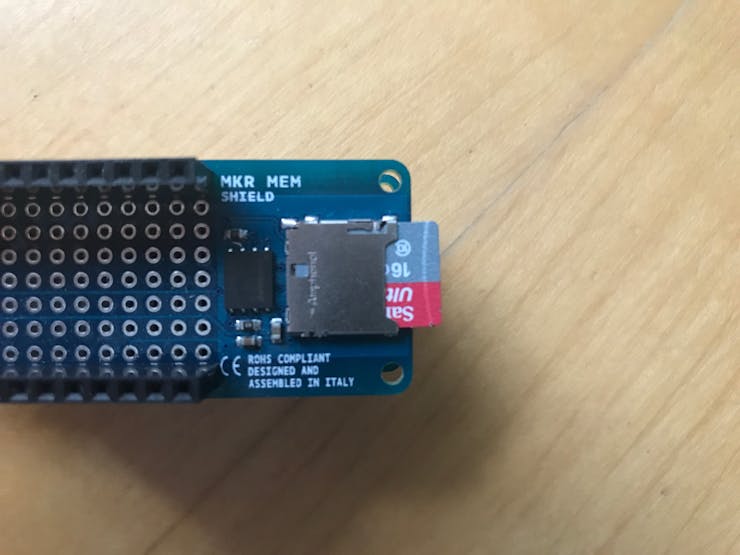
| Arduino MKR MEM Shield | × 1 | |
| GY21 Temperature and Humidity | × 1 | |
| SI1145 UV Light Sensor | × 1 | |

|
SparkFun Soil Moisture Sensor (with Screw Terminals) | × 1 |

|
Adafruit Waterproof DS18B20 Digital temperature sensor | × 1 |

|
Jumper wires (generic) | × 1 |
Hand tools and fabrication machines

|
Soldering iron (generic) | × 1 |
Story
Overview
Farming land is a precious resource, it is necessary for the survival of the modern society. But so many challenges are faced in agricultural farming, you need to get the temperature, humidity and sunlight right for the crop, and then you have to ensure that nothing destroys the crop.
The concept smart farming has been taking shape in the recent years, the idea of remotely overseeing the state of your crop. But this revolution in farming comes at a great cost, most available systems are too expensive to implement on small farms and the systems may not cover large farms.SmartAgro intends to create a network of devices, easy to use that can be placed on the field that is being monitored. The devices collect atmospheric data, soil related parameters and light values, sending all the data to the cloud where it is presented on a dashboard.
This allows any farm, any size to walk into the new age of farming, implementing a scalable fleet of devices across their land that can warn them if a drought is approaching.
VideoImage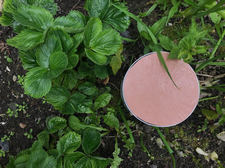

Functionality
SmartAgro allows the user to easily implement a fleet of devices on the field that is being monitored. These devices take samples from the sensors at defined intervals of time.
The data is then logged to a.csv file on an SD card and sent to the backend where the data is visualised on a dashboard. The project consists of a front-end and a backend.
Front-EndThe front-end of the project refers to the physical devices placed on the field. These devices take samples of data from their sensors, burning them to an SD card and sending the data to the backend. Below is the functionality overview of the project.
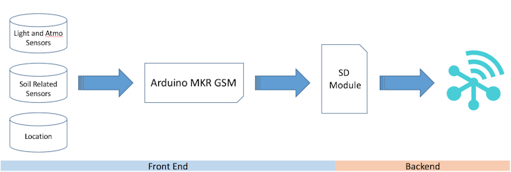
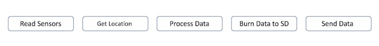
An MKR GSM is used for the front-end, the device collects the data and then sends it to Soracom, where it is visualised. Below are the steps taken by the device when collecting data.
The device starts off in setup mode, here it prepares all the sensors and gets a location fix. The device then checks to see if there is already a file to burn to on the SD card, if a file is available, it will append to it, otherwise, the device will create a file and append to it.
The device then takes samples from all its sensors, it measures atmospheric temperature and humidity, soil moisture and temperature and UV index, visible light and IR light. These values are then stored on the device.
The MKR GSM then prepares the data for burning it to the SD card, it compiles the data into a string that represents a line of a.csv file.
The data is then burned to the SD card.
All the values are then prepared to be sent to Soracom through GSM. The data is compiled into a JSON buffer.
The data is then sent to the backend by the device. The device now goes into sleep mode for a defined amount of time and will repeat the process when it wakes up.
 SDCard
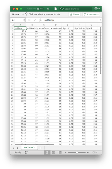
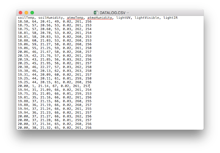
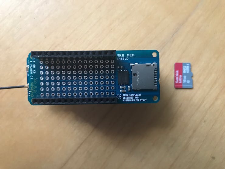
The device will log the data acquired from the sensors to the SD card attached to it. The data will be appended to a.csv file that can then be downloaded.
In the setup, the device locates if a.csv file to write to is available and will append to it if it already exists. It will create a new file if one does not exist. Below are some images of the file.
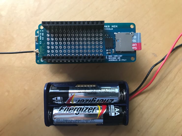
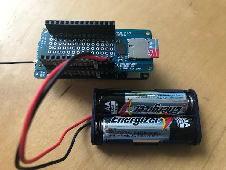
 Battery
The device can be powered through multiple ways. It can be powered by a LiPo battery through the provided port on the device, by a power bank or by connecting a battery through the VIN port on the device.
The lifetime of the device heavily relies on the power of the battery. The device goes into sleep mode between reads to conserve as much energy as possible.
Data SendThe data is sent to Soracom through a GSM connection to the server. The data is sent as a JSON payload. This data is then received by the backend and is then processed. Below is an example of the payload.
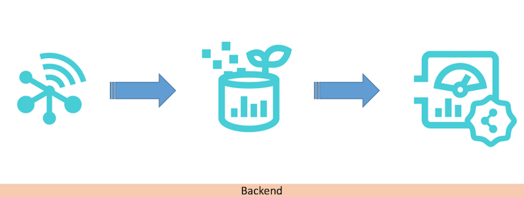
{ "Latitude":53.3570404, "Longitude":-6.2609935, "soilTemp":20.56, "soilHumidity":40, "atmoTemp":22.12, "atmoHumidity":62, "uvLight":0.00, "irLight":257, "deviceName":"device1" } BackendThe backend of the application refers to Soracom. The data is received by Soracom, processed and then displayed on the dashboard.
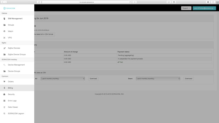
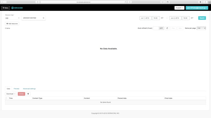
Data is received by Soracom through Soracom Air
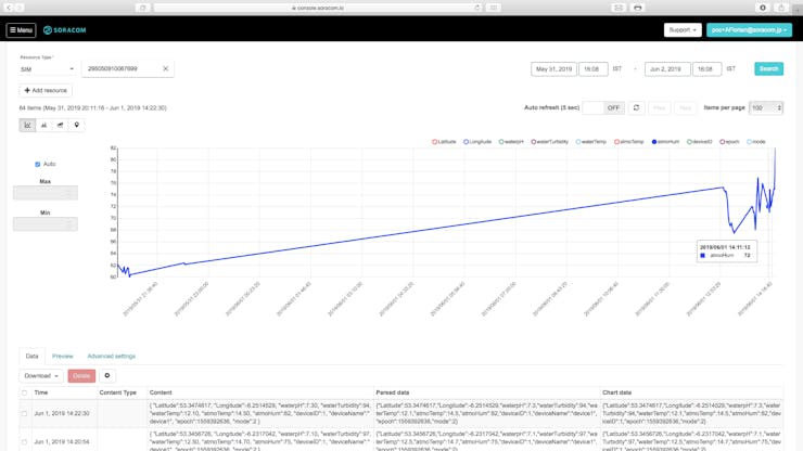
The data is then collected by Soracom Harvest
The data is finally queried by Soracom Lagoon at intervals of time which then displays the data on a dashboard.
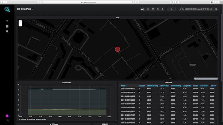
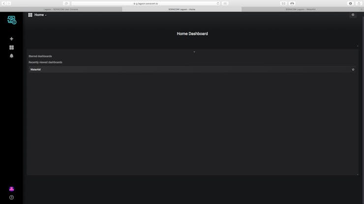
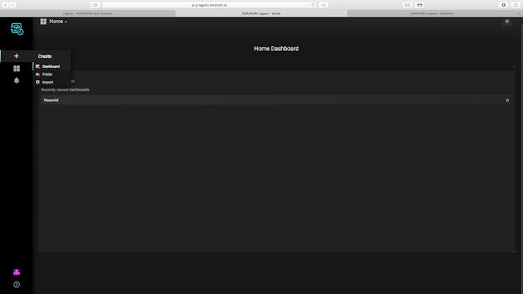
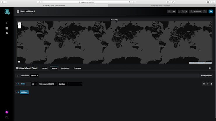
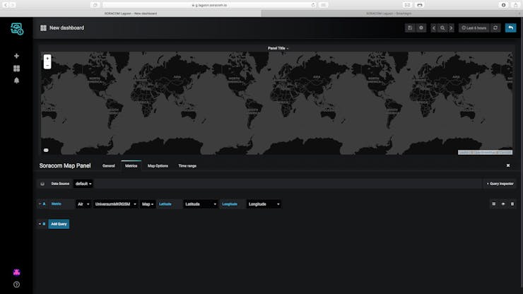
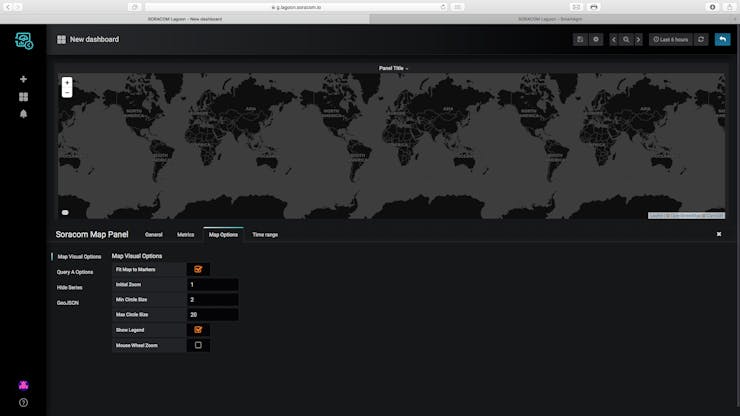
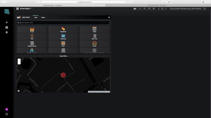
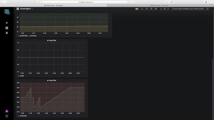
 The Dashboard
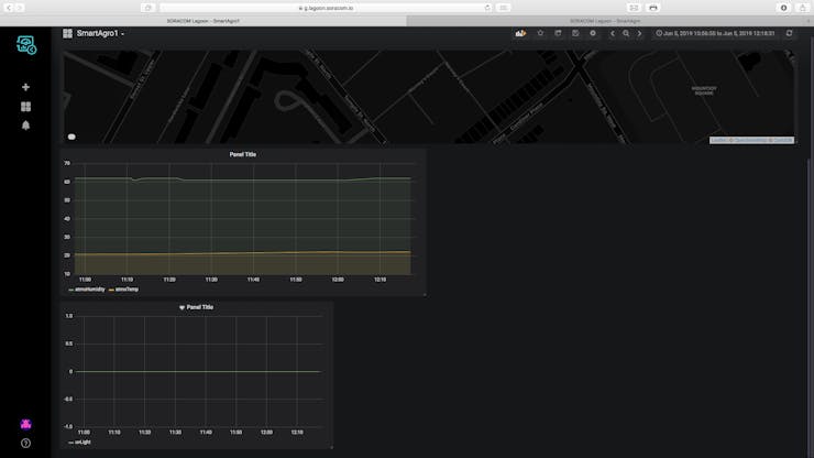
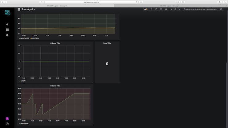
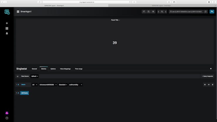
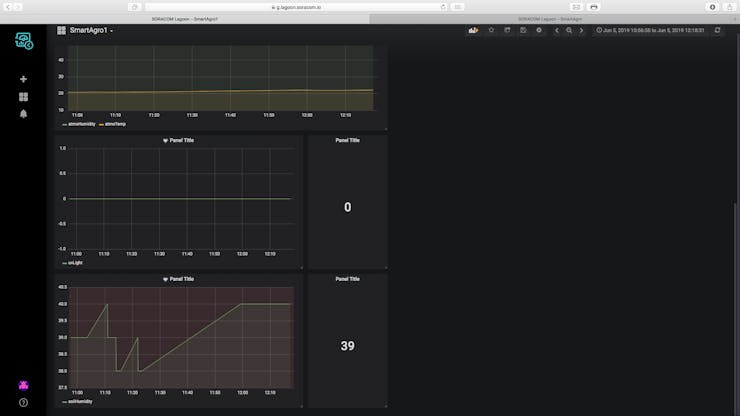
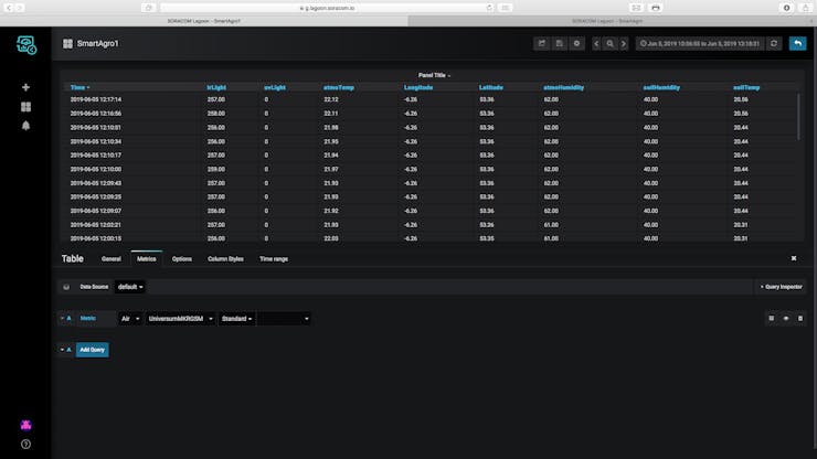
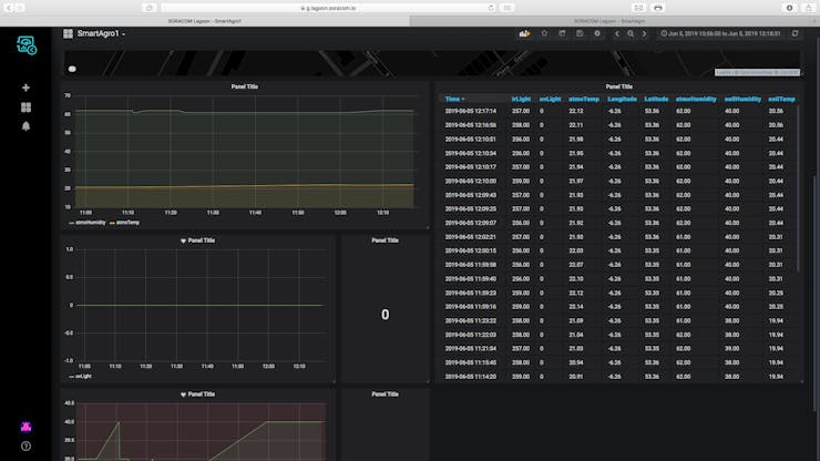
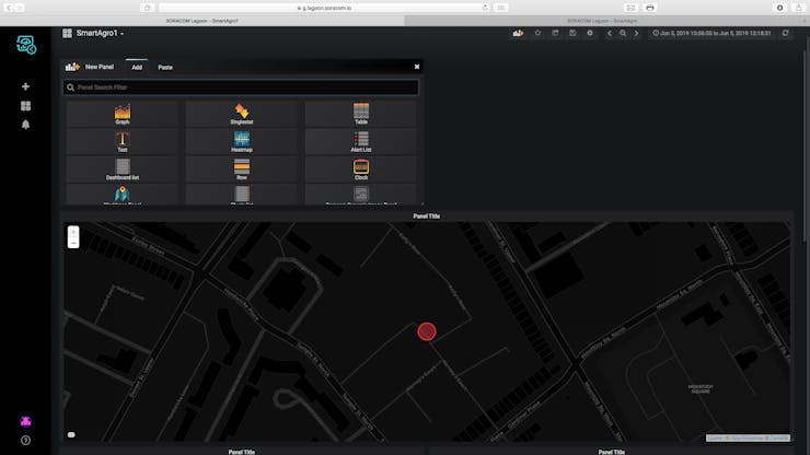
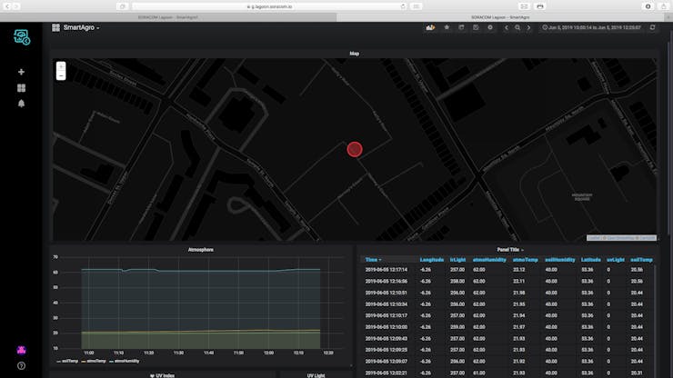
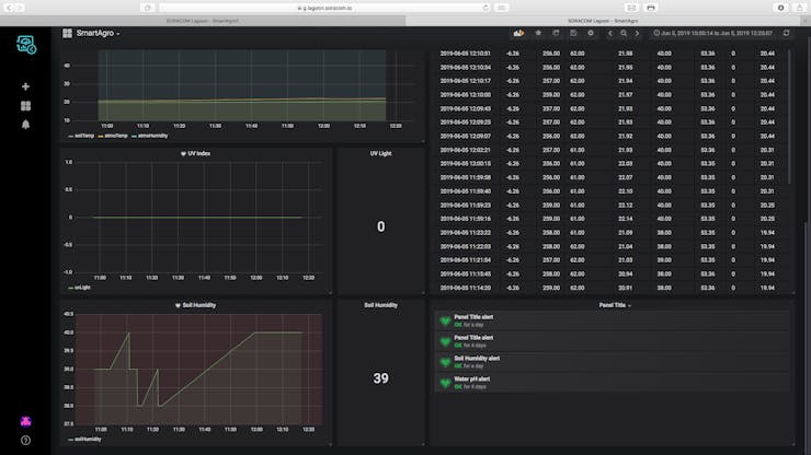
The dashboard for the project is hosted on Soracom Lagoon. The data is received by Soracom Air in the backend, Soracom Harvest collects the data and then Lagoon queries it from Harvest.
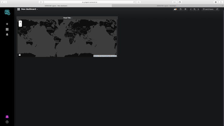
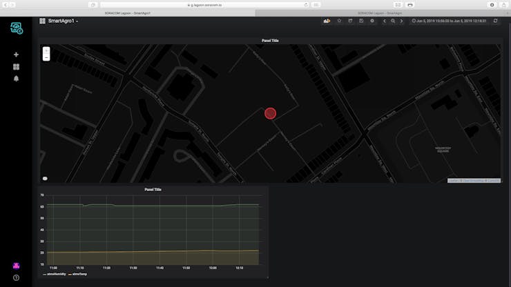
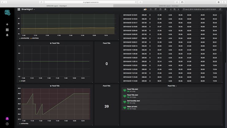
The location of each device in the fleet and all sensor data is plotted on the dashboard. Screenshots of the dashboard are below.
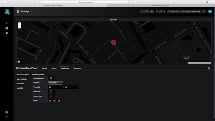
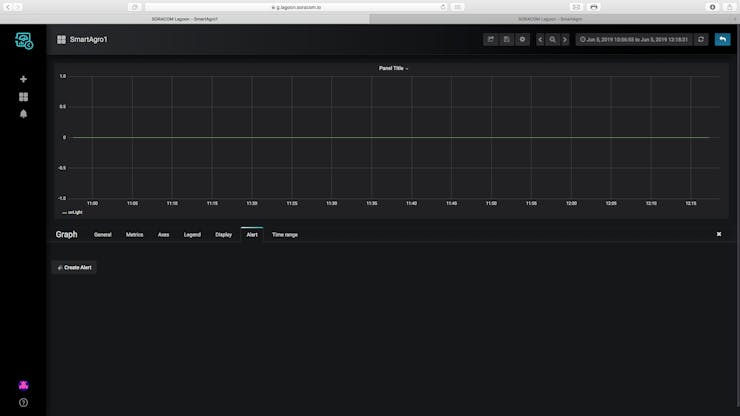
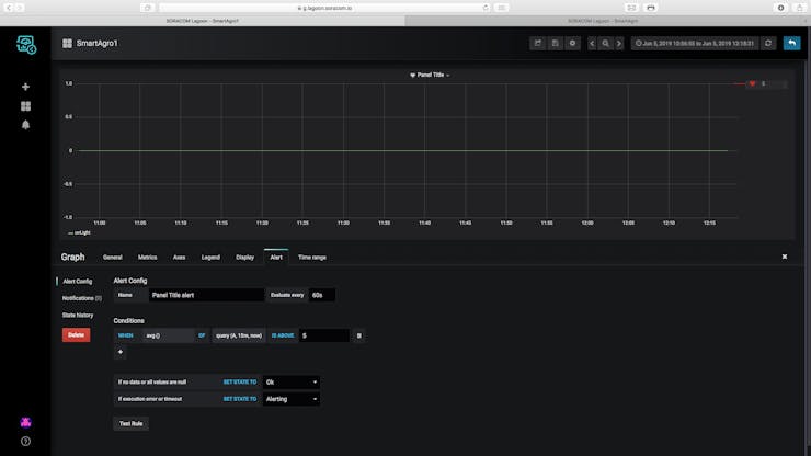
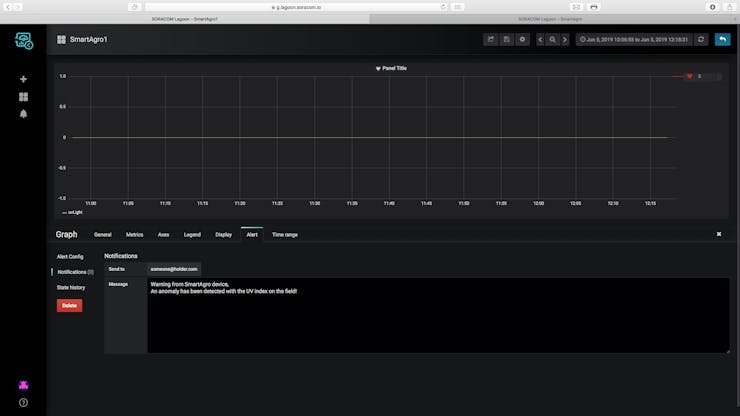
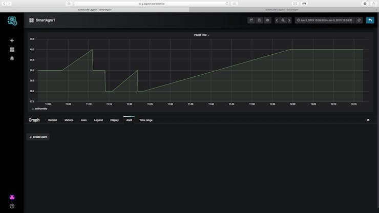
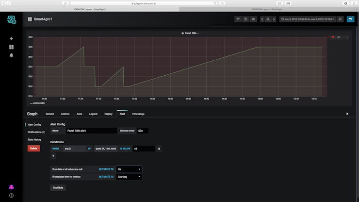
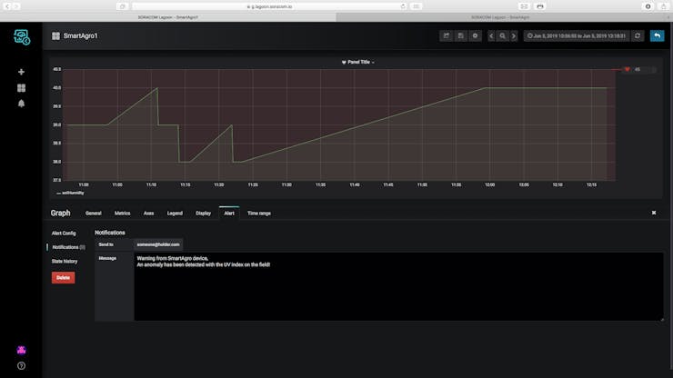
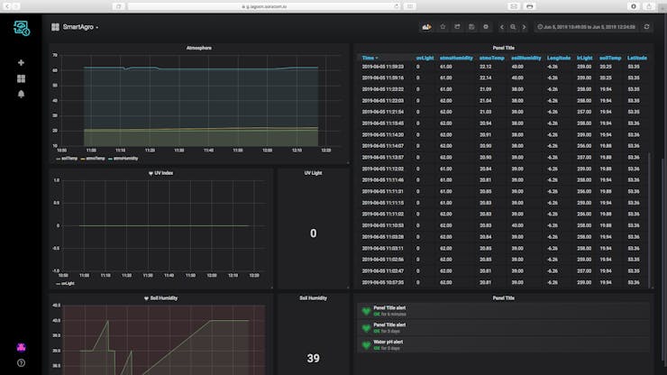 Alerts
The user can also set the backend to receive email notifications if the UV index or soil humidity collected by the device are abnormal. This way, the user will know if the crops need attention.
Benefits
The user operating this project will have many benefits:Constructing the Project
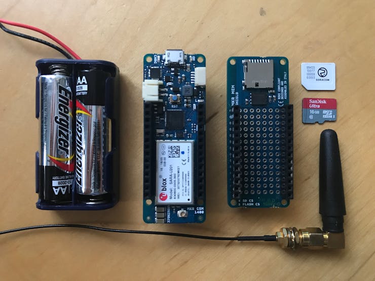
Step 1: Required ApparatusThis project requires a list of sensors and other materials. The complete list of materials needed is below.
1, Arduino MKR GSM1, Arduino MEM Shield1, GY-21 temperature and humidity module1, Waterproof temperature sensor1, SI-1145 UV Light Sensor1, Soil Moisture Sensor1, 2AA Battery Box (with batteries) or a LiPo battery1, Soracom Sim Card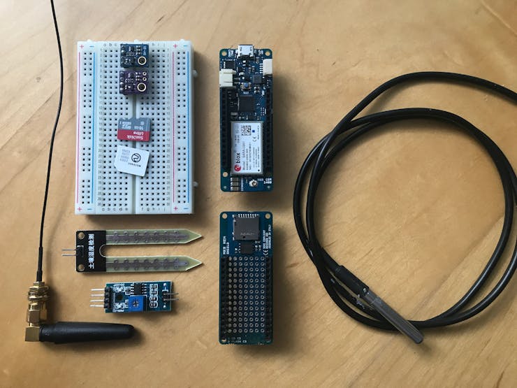 Step 2: Connecting the Circuit
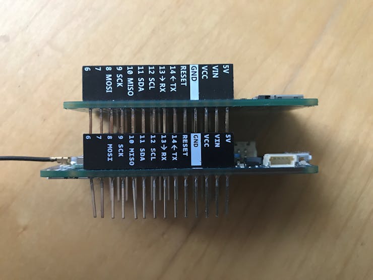
A soldering iron will be needed to solder all the components together. The schematics are illustrated in the fritzing file below.
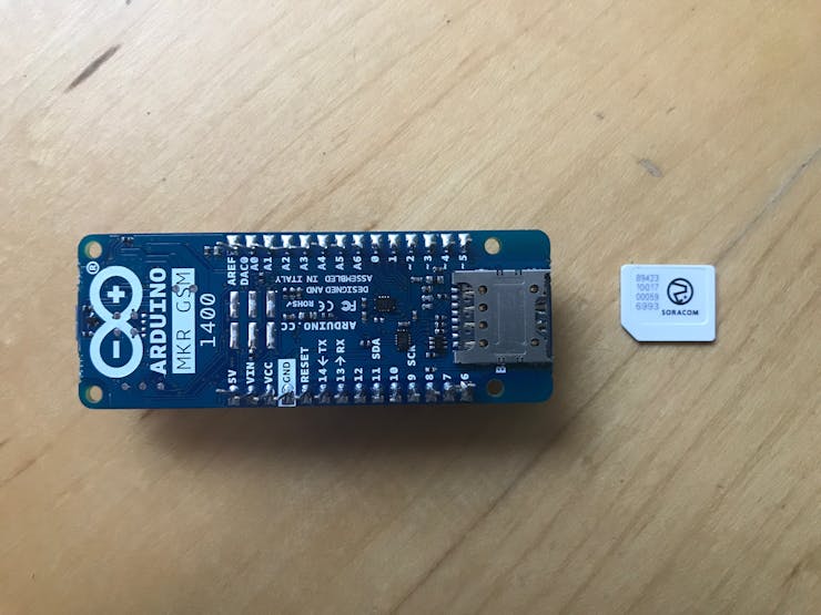
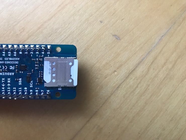
Remember to attach the MEM shield to the board!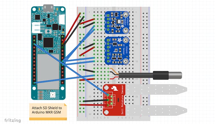 Preparing the MKR GSM
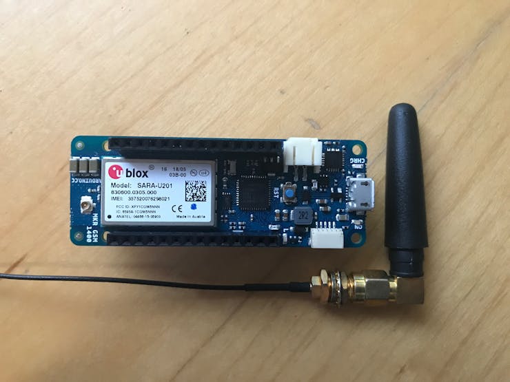
The Arduino MKR GSM needs to be prepared. I powered the board with 2 AA batteries through the VIN port. The steps are below.
 Step 3: Acknowledging the Code
There are 4 main sections to the code used for the project.
All these sections are described and detailed below.
Prepare SD bool createFile() { // create the .csv file in the SD card Serial.println("Creating File"); Serial.println(" OK - Creating and Opening File"); File dataFile = SD.open("datalog.csv", FILE_WRITE); if(dataFile) { Serial.println(" OK - File Created"); Serial.println(" OK - Appending Legend to File"); Serial.print(" OK - Appending "); Serial.println(legend); dataFile.println(legend); dataFile.close(); Serial.println(" Success - Data Appended"); } else { Serial.println(" Error - File Not Detected"); Serial.println(" OK - Trying Again in 5 seconds"); Serial.println("________________________________________"); Serial.println(""); dataFile.close(); delay(5000); return false; } Serial.println("________________________________________"); Serial.println(""); return true; } void checkFile() { Serial.println("Checking .csv"); Serial.println("________________________________________"); Serial.println("Setting Up File"); Serial.println(" OK - Checking for File Presence"); if(SD.exists("datalog.csv")) // check if the .csv file already exists { // append to the existing file is it exists Serial.println(" OK - File Exists"); Serial.println(" OK - Will Append to Existing File"); Serial.println("________________________________________"); Serial.println(""); } else { // create a new file to append to Serial.println(" OK - File Not Present"); Serial.println(" OK - Creating File"); Serial.println(""); while(!createFile()) {}; } } ThecheckFile() function checks if the.csv file that the device is supposed to append to exists. If the file exists, the function ends, otherwise it calls on createFile() which creates a new.csv file to append to.CollectDatavoid collectData()
{
Serial.println("Gathering Data");
Serial.println("________________________________________");
Serial.println("Getting Data from Sensors");
Serial.println(" OK - Contacting all Sensors");
// collecting data from all sensors
soilSens.requestTemperatures();
soilTemp = soilSens.getTempCByIndex(0);
soilHumidity = analogRead(A1);
soilHumidity = map(soilHumidity, 1023, 0, 0, 100);
atmoTemp = gy21.readTemperature();
atmoHumidity = gy21.readHumidity();
visibleLight = uv.readVisible();
irLight = uv.readIR();
rawUVLight = uv.readUV();
uvLight = (rawUVLight / 100);
Serial.println(" OK - Data Collected");
Serial.println(" OK - Dumping Data");
Serial.print("[Light] Visible "); Serial.println(visibleLight);
Serial.print("[Light] Infrared "); Serial.println(irLight);
Serial.print("[Light] Ultraviolet "); Serial.println(uvLight);
Serial.print("[Atmo] Temperature "); Serial.println(atmoTemp);
Serial.print("[Atmo] Humidity "); Serial.println(atmoHumidity);
Serial.print("[Soil] Temperature "); Serial.println(soilTemp);
Serial.print("[Soil] Humidity "); Serial.println(soilHumidity);
Serial.println(" Success - Data Dumped");
Serial.println("________________________________________");
Serial.println("");
}
This section of code collects data from all the sensors on board. It contacts sensors for atmospheric temperature and humidity, soil moisture and temperature and UV index, IR light value and visible light.
Burn Data to SDbool burnData(String data) { Serial.println("Burning Data"); Serial.println("________________________________________"); Serial.println("Burning Data to SD Card"); Serial.println(" OK - Opening File"); File dataFile = SD.open("datalog.csv", FILE_WRITE); if(dataFile) { Serial.println(" OK - File is Present"); Serial.print(" OK - Appending "); Serial.println(data); Serial.println(" OK - Burning data"); dataFile.println(data); // burn the data to the SD card dataFile.close(); Serial.println(" Success - Data Appended"); Serial.println("________________________________________"); Serial.println(""); } else { Serial.println(" Error - File Not Present"); Serial.println(" OK - Trying Again in 5 Second"); Serial.println("________________________________________"); Serial.println(""); delay(5000); } Serial.println(""); }This function burns the data that was previously compiled into a line of a.csv file to the SD card. The data is appended to the file on the card.
Send Data to Soracomvoid parseData(String dataToSend) { Serial.println("Sending Data"); Serial.println("________________________________________"); Serial.println("Sending Data to Soracom"); Serial.println(" OK - Setting Up Connection"); if(client.connect(url, 80)) // prepare connection and format send { Serial.println(" OK - Connection Established, Parsing Data"); client.println("POST / HTTP/1.1"); client.println("Host: harvest.soracom.io"); client.println("User-Agent: Arduino/1.0"); client.println("Connection: close"); client.print("Content-Length: "); client.println(dataToSend.length()); client.println(""); client.println(dataToSend); Serial.println(" OK - Data Parsed"); } Serial.println(" OK - Getting Responce"); Serial.println(""); // read back from server while(1) { if(client.available()) { char c = client.read(); Serial.print(c); } if(!client.connected()) { break; } } Serial.println(" Success - Data is Parsed"); Serial.println("________________________________________"); Serial.println(""); }Finally, the data is sent to Soracom. The device established a connection with the server and then prepares the credentials. The data is then sent to the server and the response is printed to the Serial Monitor.
The device then goes to sleep for a defined amount of time repeating the steps again.
Step 4: Setting Up the VariablesA few variables have to be edited by the user before he project can be used. The variables that are editable are in the main file of the code. These are described below.
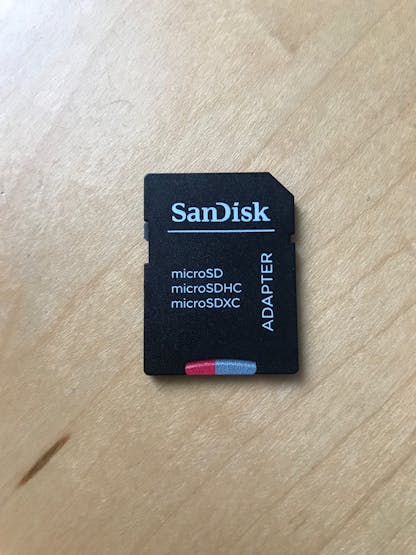
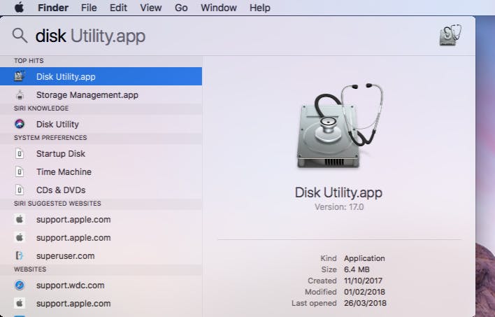
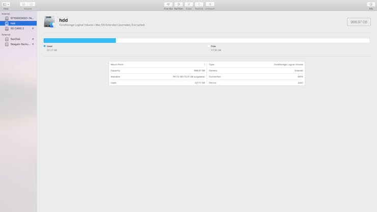
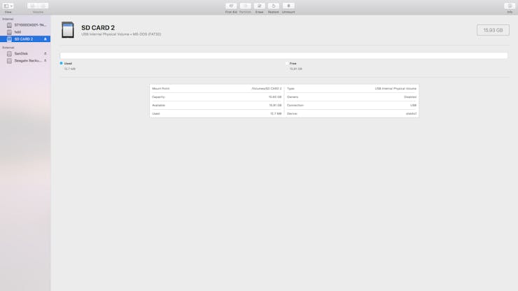
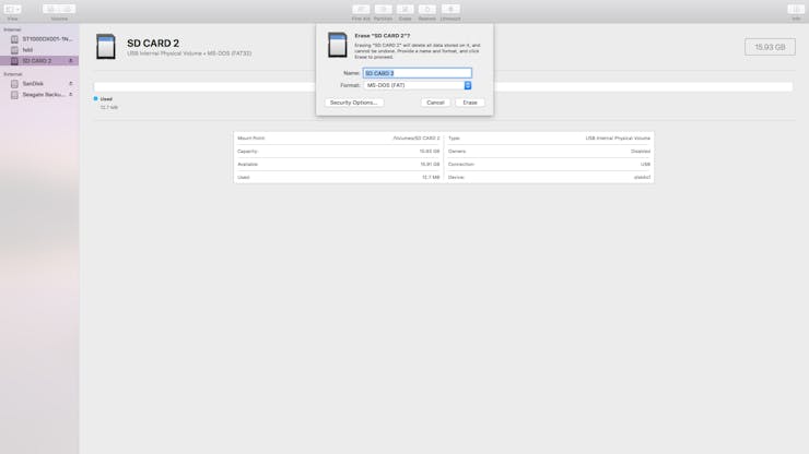
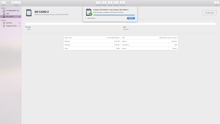
deviceName represents the custom name of the device. This is sent together with the payload to Soracom, it is useful to identify devices apart when managing a fleet of devices.sleepTime is the amount of time (in milliseconds) that the device will sleep for between reads. The device will go to sleep between reads to reduce the battery consumed.proDebug is set to true if bugging and to false otherwise. If proDebug is enabled, the device requires to be connected to a computer with the serial monitor on to work. Set to true when debugging but ensure it is set to false if it is on the field. Note that the device will still print to the serial even if proDebug is false;Step 5: Setting Up the SD CardThe SD card has to be prepared before it can be used with the device. The SD card has to be formatted as FAT 32. Follow the steps below for preparing the SD card.

 Step 6: Upload the Code
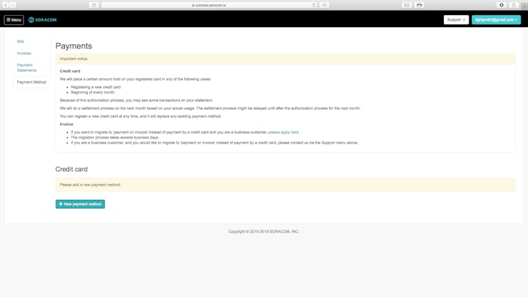
Before setting up the backend, data has to be sent to it.
If you do not have a Soracom account and the SIM you are using is not registered, you will have to complete step 7 first.To do this, connect your MKR GSM to your computer and upload the code to the device, ensure that the mode of the device is set to 1 for this setup. After the code has uploaded, place all the sensors in water.
Now press the button on the device and wait for the data to collect and send. Repeat this a couple of times to populate Soracom Air.
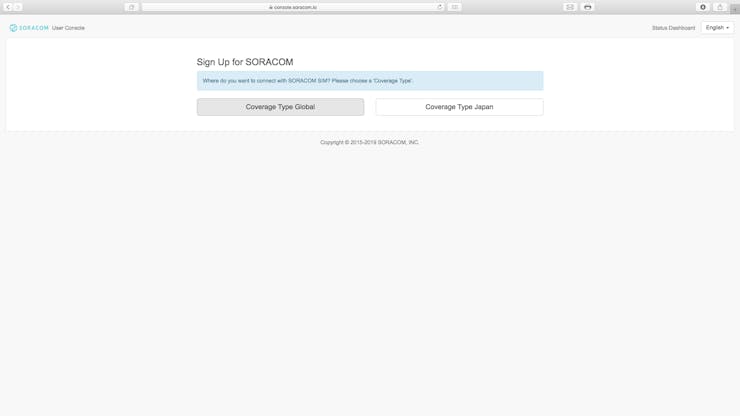
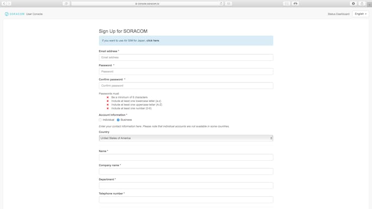
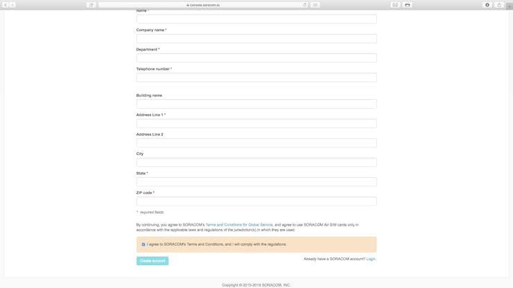
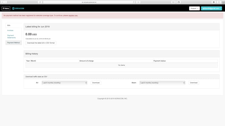
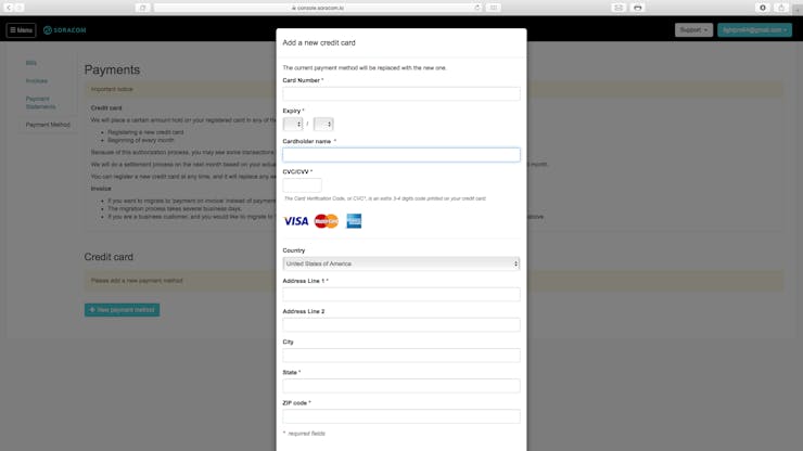
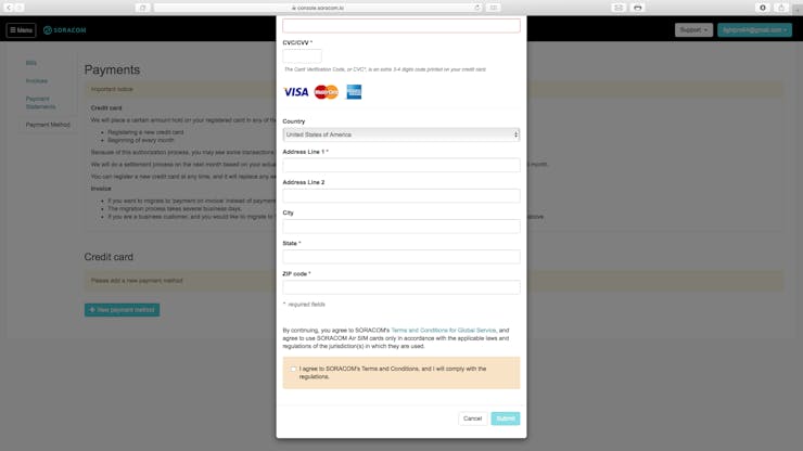
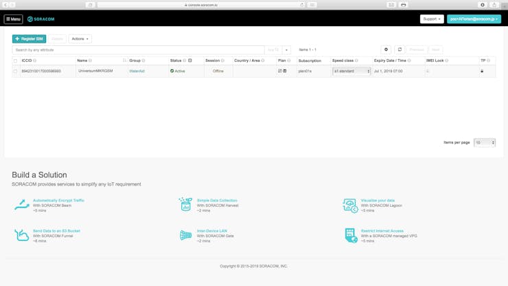
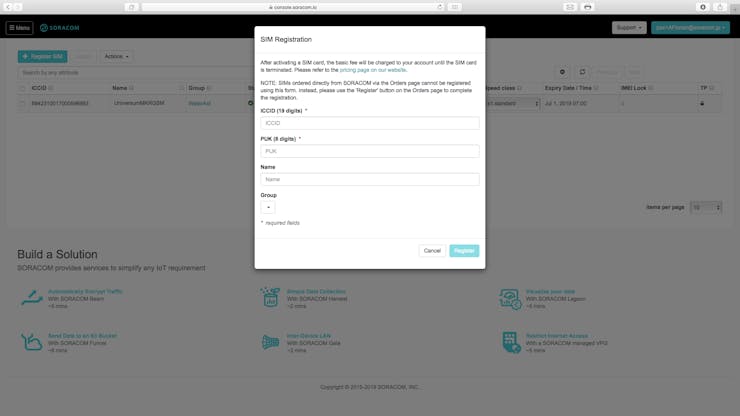
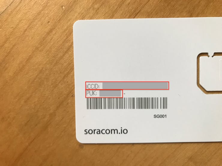
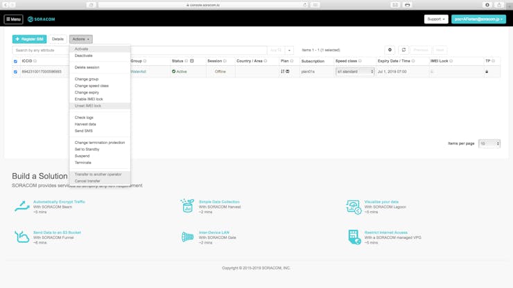
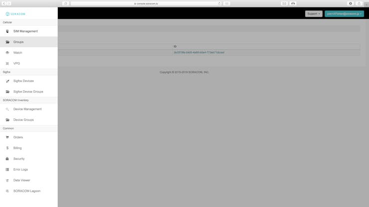
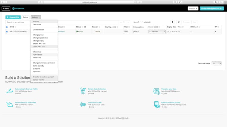
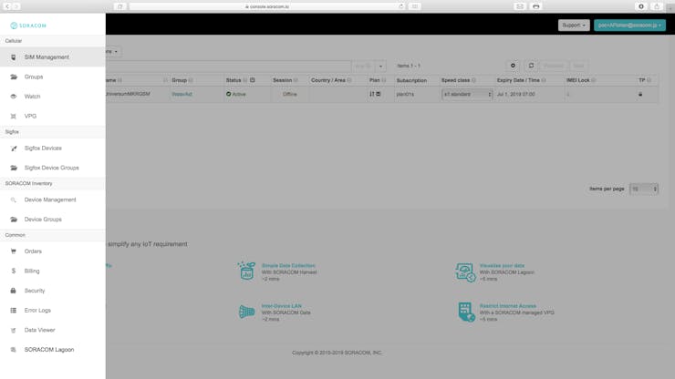
Step 7: Setting Up SoracomThis step is split into 2 sections, the first will cover creating an account with Soracom and registering your SIM while the other will cover setting up Soracom Harvest to collect the data from Air. If you already have an account with Soracom, skip the first section.
Section 1: Creating an Account

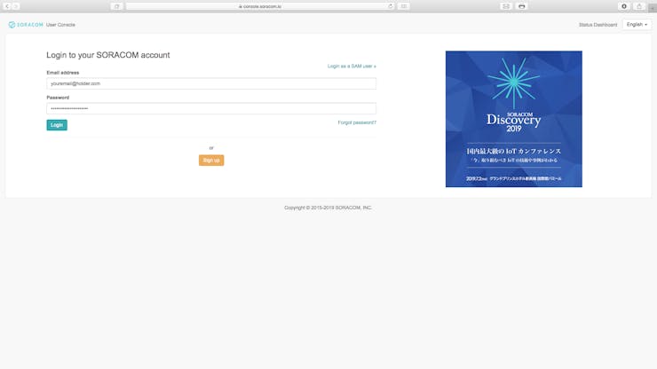
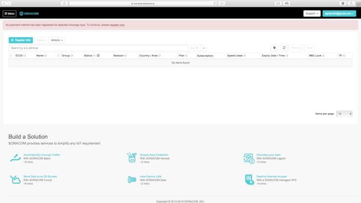

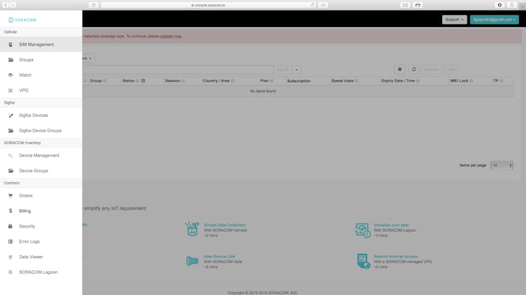
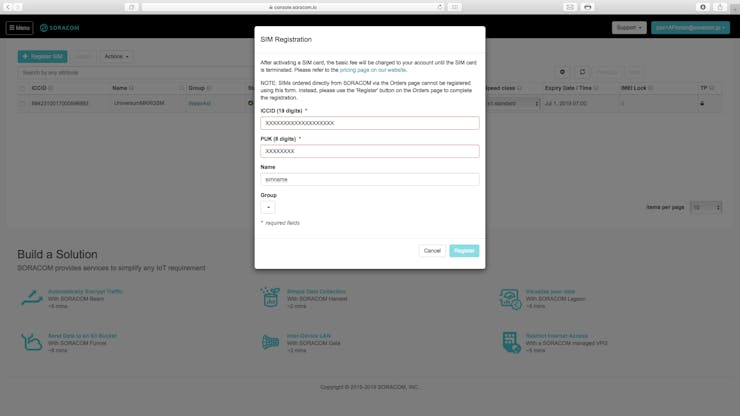
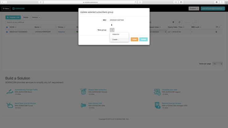
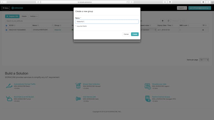
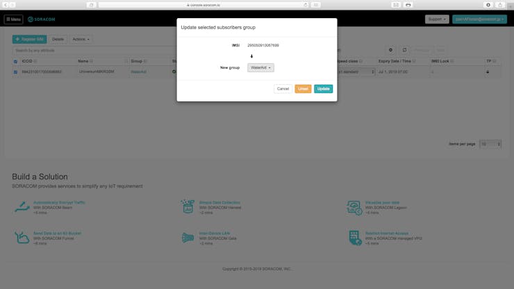
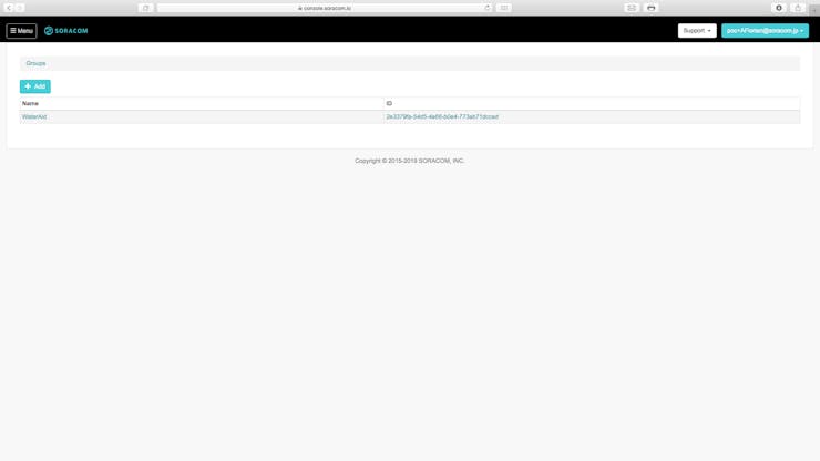
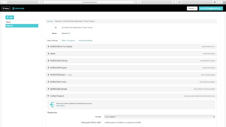
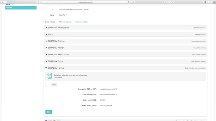
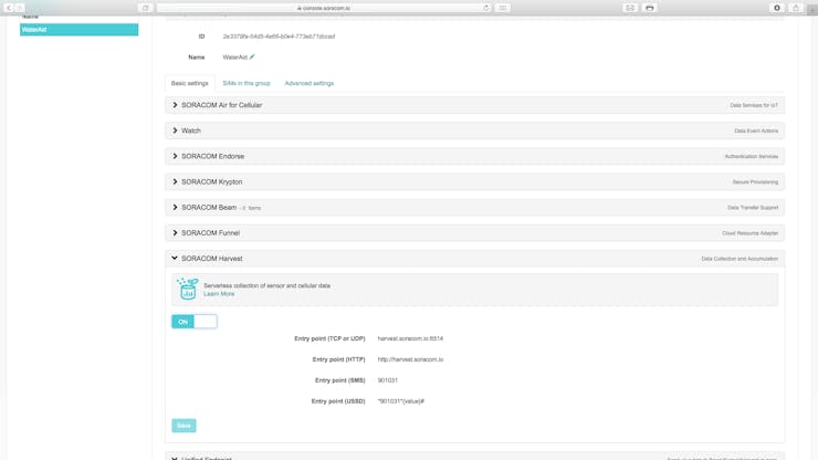
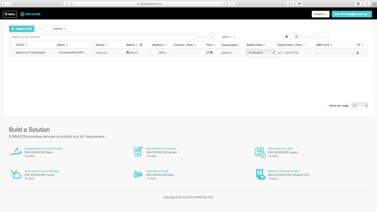 Section 2: Groupsand Harvest
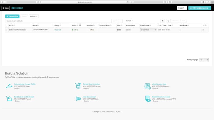


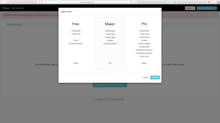
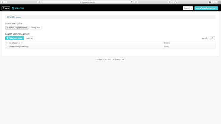
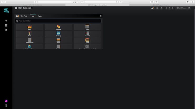
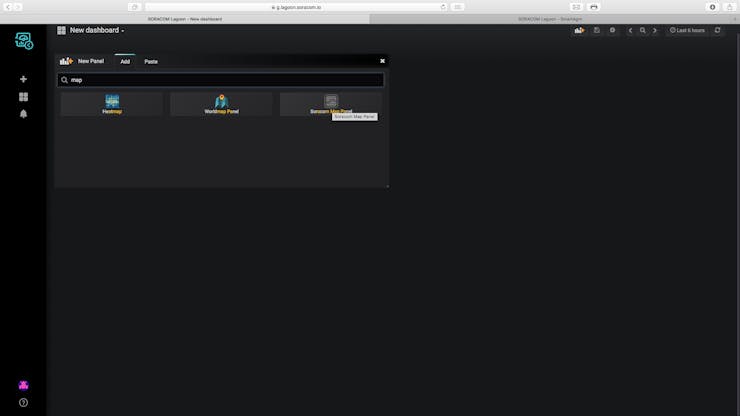
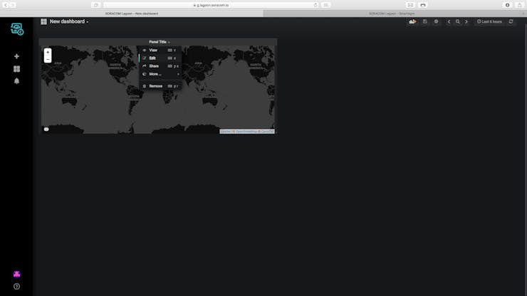
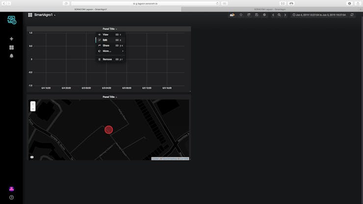
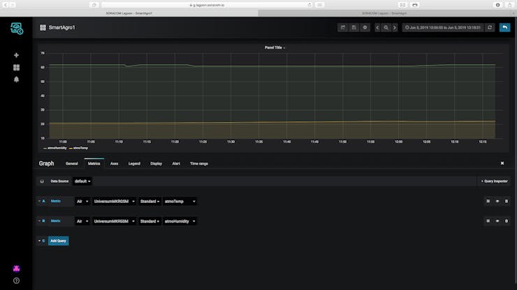
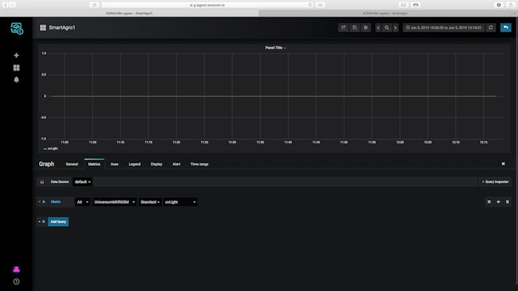
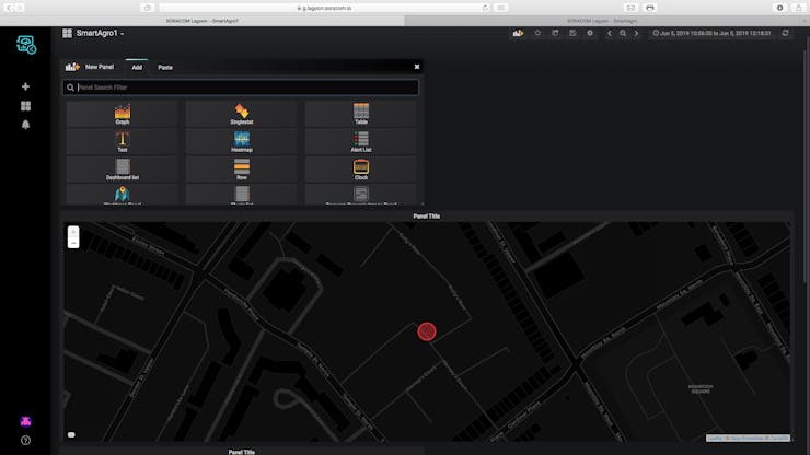
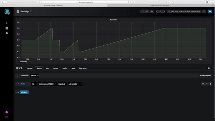
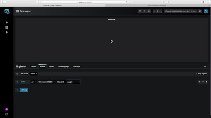
 Step 8: Setting Up Soracom Lagoon
The last thing to set up on Soracom is Lagoon, this is the tool that we will use to visualise our data and create email alerts if the data is not good. Follow the steps below.


 Libraries
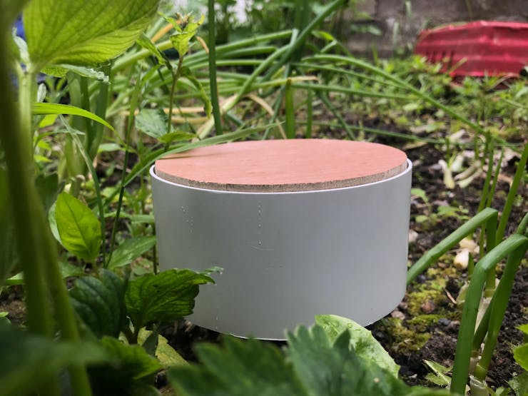
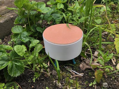
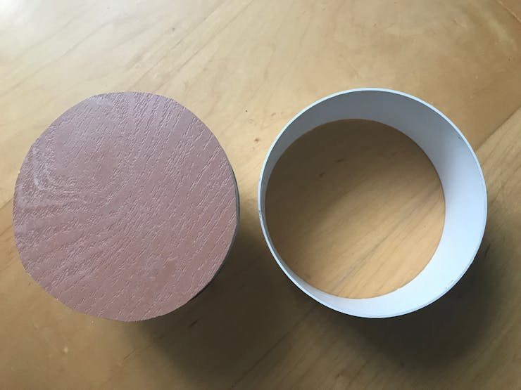
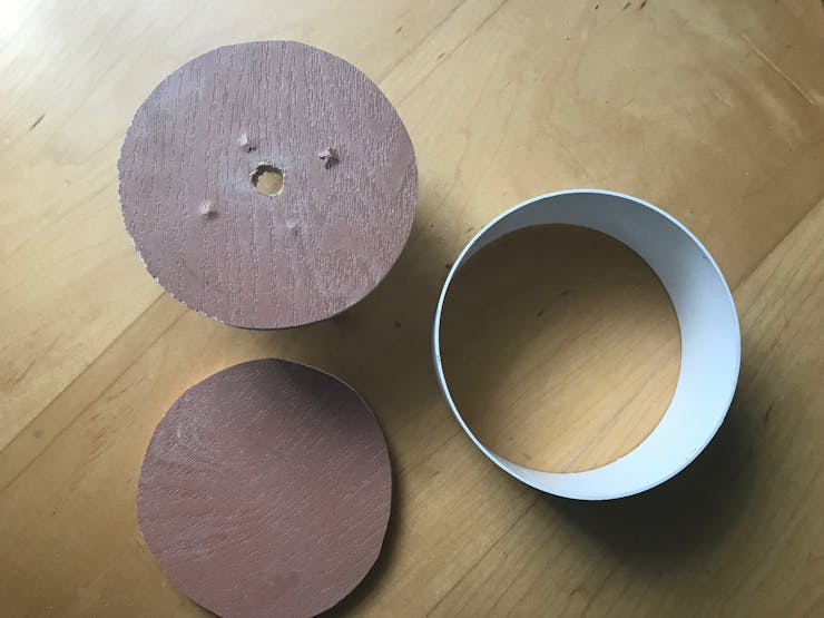
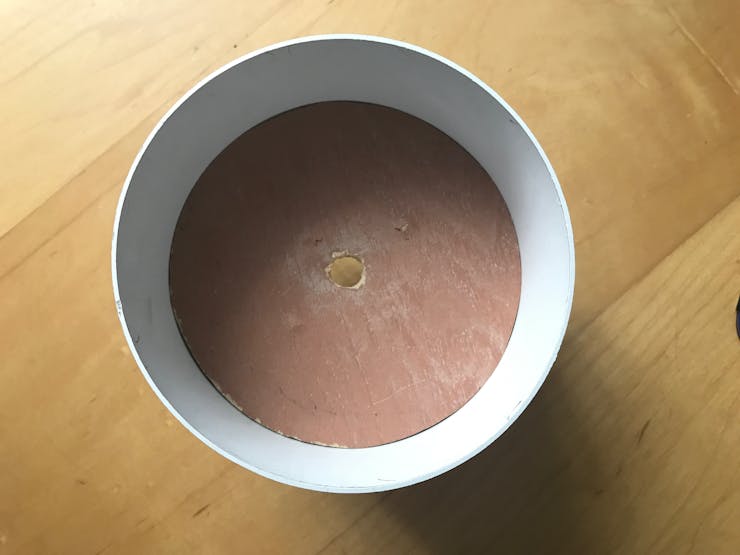
Finally I designed an enclosure for the project, it would be preferable if the top of the enclosure would be transparent so that the UV sensor can be placed within the enclosure, I placed my sensor outside the enclosure to prevent any interference.
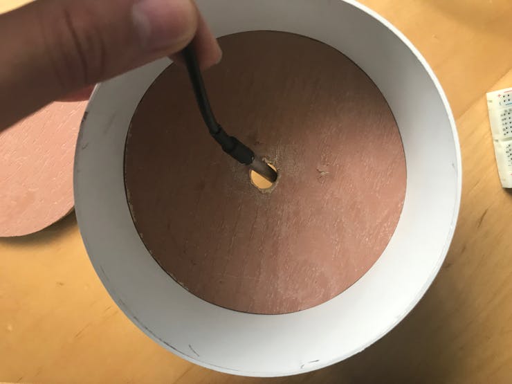
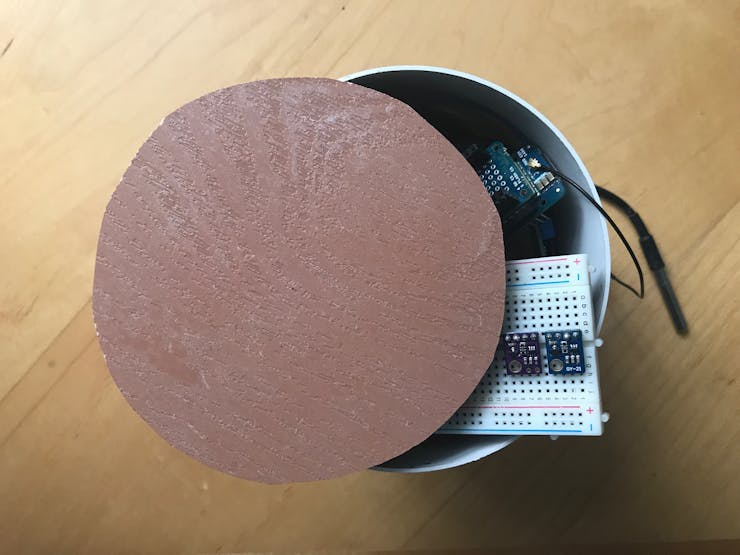
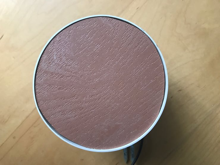
Finally, ensure that all the variables are set and then place the device on the field, it should be ready to monitor all parameters now.
Using an SD Card ModuleI have chosen to use the Arduino MKR MEM shield as it is easy to use and quite compact. An SD card module can also be used though most operate with 5v while the MKR GSM can only provide 3.3v, therefore a level convertor is needed to step up the 3.3v to 5v.
Background
I came up with this idea while going on a bus past fields. I remembered reading about new devices used to monitor agricultural fields but I was made aware of the costs which are mostly not affordable for farmers.
So I decided to use the low cost Arduino to monitor multiple parameters on the farm and allow any farm, big or small to step into the age of IoT and smart farming.